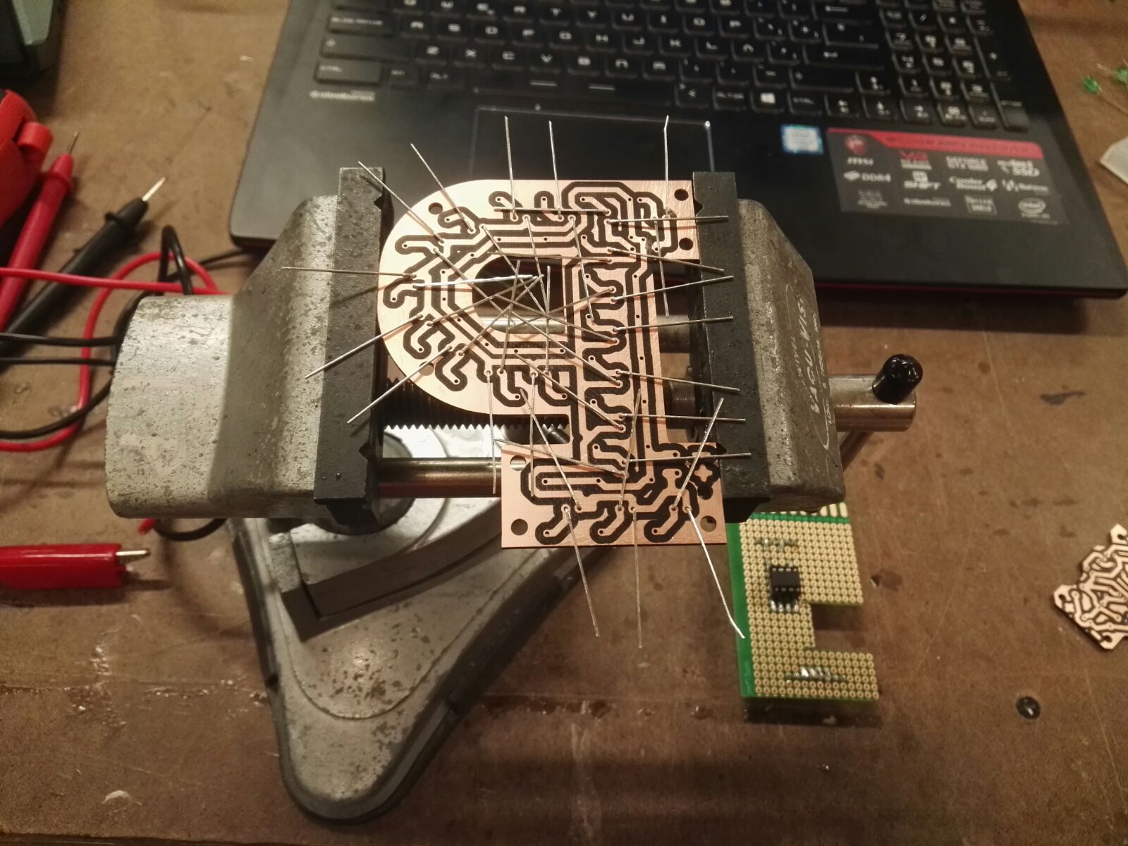
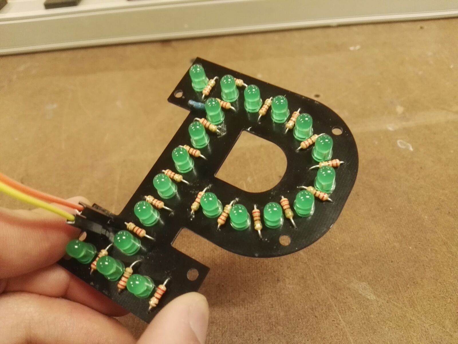
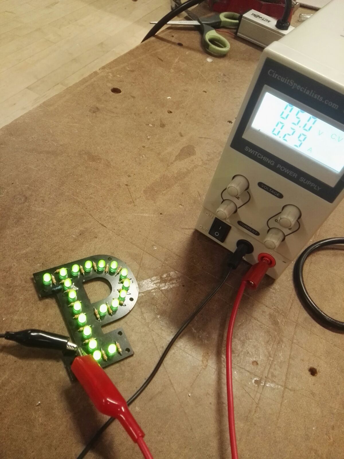
This is the conclusion of the previous posts related with two PCB. The first board is the letter "P" drawn by 20 LEDs. The second board is a ATTiny85 module with transistor (TP-120) in order to control >5v. This latter one includes one digital input (switch) and a digital output (LED), two capacitors to normalize peaks and header to daisy chain.
These boards took 14 hours of my life. My first huge mistake was choosing 220K resistors instead of 220 ohms (three order of magnitude wrong). I had to desolder and soldered again every resistor (20 resistors - 40 holes). Recommendation: Test your board (breadboarding) before soldering.


